Displaying 1 - 10 of 19
Dr A Röschl's picture

PACEMAKER ECG: PSEUDOFUSION - FUSION

Here is a Pacemaker ECG with no signs of PM malfunction: Beat A is an intrinsic beat (atrial fibrillation). Beat B is a pseudofusion beat. Beat C is a fully paced beat. Beat D is a fusion beat. Ventricular fusion is the electrical summation of an intrinsic beat of the heart and depolarization from a pacing stimulus. The morphology lies between a fully paced beat and a complete intrinsic beat.

Dawn's picture

Ask The Expert

Today’s expert is Dr. Jerry W. Jones, MD, FACEP, FAAEM

Jerry W. Jones, MD FACEP FAAEM is a diplomate of the American Board of Emergency Medicine who has practiced internal medicine and emergency medicine for 35 years. Dr. Jerry JonesDr. Jones has been on the teaching faculties of the University of Oklahoma and The University of Texas Medical Branch in Galveston. He is a published author who has also been featured in the New York Times and the Annals of Emergency Medicine for his work in the developing field of telemedicine. He is also a Fellow of the American College of Emergency Physicians and a Fellow of the American Academy of Emergency Medicine and, in addition, a member of the European Society of Emergency Medicine. 

 Dr. Jones is the CEO of Medicus of Houston and the principal instructor for the Advanced ECG Interpretation Boot Camp and the Advanced Dysrhythmia Boot Camp. 


Question:   What is the cause of an apparent right bundle branch block pattern in a paced rhythm?

Answer:  Is There a Pacemaker Wire Problem… or Not?

 During one of my orientations as a young internal medicine house officer, the cardiologist lectured to us on the essentials of how to check pacemakers. Since none of us had any ECG interpretation background our comprehension was less than sterling. But I remember him stressing the point that a properly paced pacemaker lead would result in a left bundle branch block pattern on the ECG. A right bundle branch block pattern in V1, on the other hand, meant that the pacemaker wire had inadvertently wandered into the left ventricle – a highly undesirable situation. 

“Not to worry,” he said. “Such things rarely happen and you will probably retire before seeing such a thing!” That evening I saw my first pacemaker 12-lead ECG with a right bundle branch block pattern in V1. Fate wasted no time with me.

I ordered a 3-view chest x-ray and as far as I could see, the wire looked like it was in the right ventricle where it was supposed to be. I called the cardiologist on-call who happened to be in the hospital at the time and he dropped by the ward. Back then, we didn’t have ultrasound or echo available. But he, too, was convinced the pacemaker wire was in the right ventricle. It really was and so I still hadn’t seen a RBBB pattern due to a pacer wire in the left ventricle. I still haven’t, but I have seen a number of pacemaker ECGs with a RBBB pattern in V1.

How do we know if such a finding represents a real left ventricular pacer wire or a pseudo-malplacement?

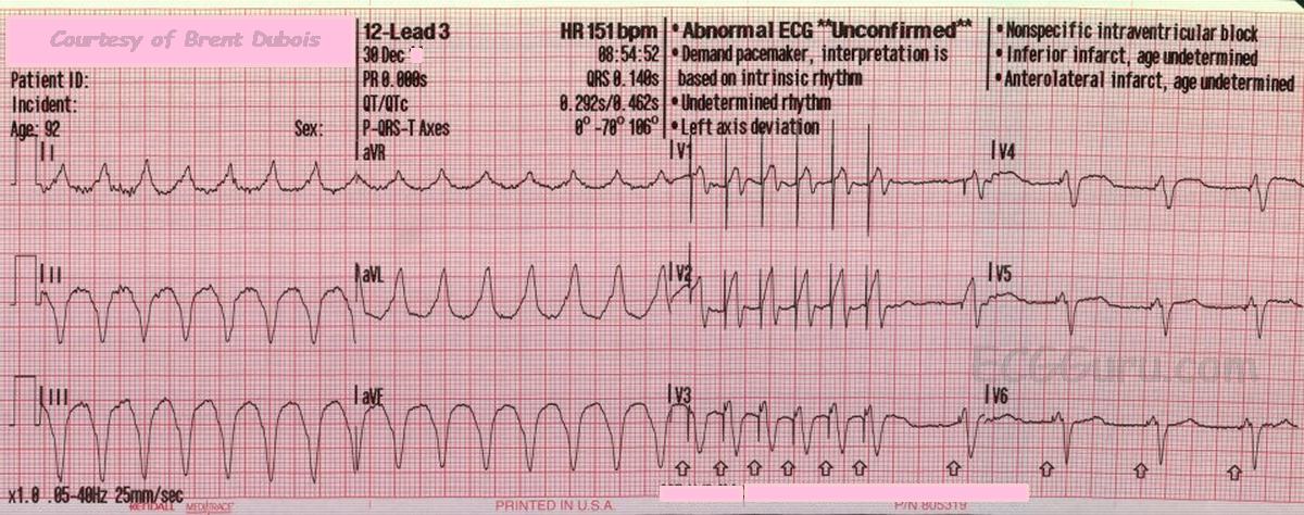
First, just be aware that a wire that really IS in the left ventricle is going to present with a RBBB pattern in V1. It will NOT ever present with a LBBB pattern. However, a wire that has been correctly placed in the RIGHT ventricle can – from time to time – present with a RBBB pattern in V1. In my years as an attending in the emergency department, I saw this seven or eight times.

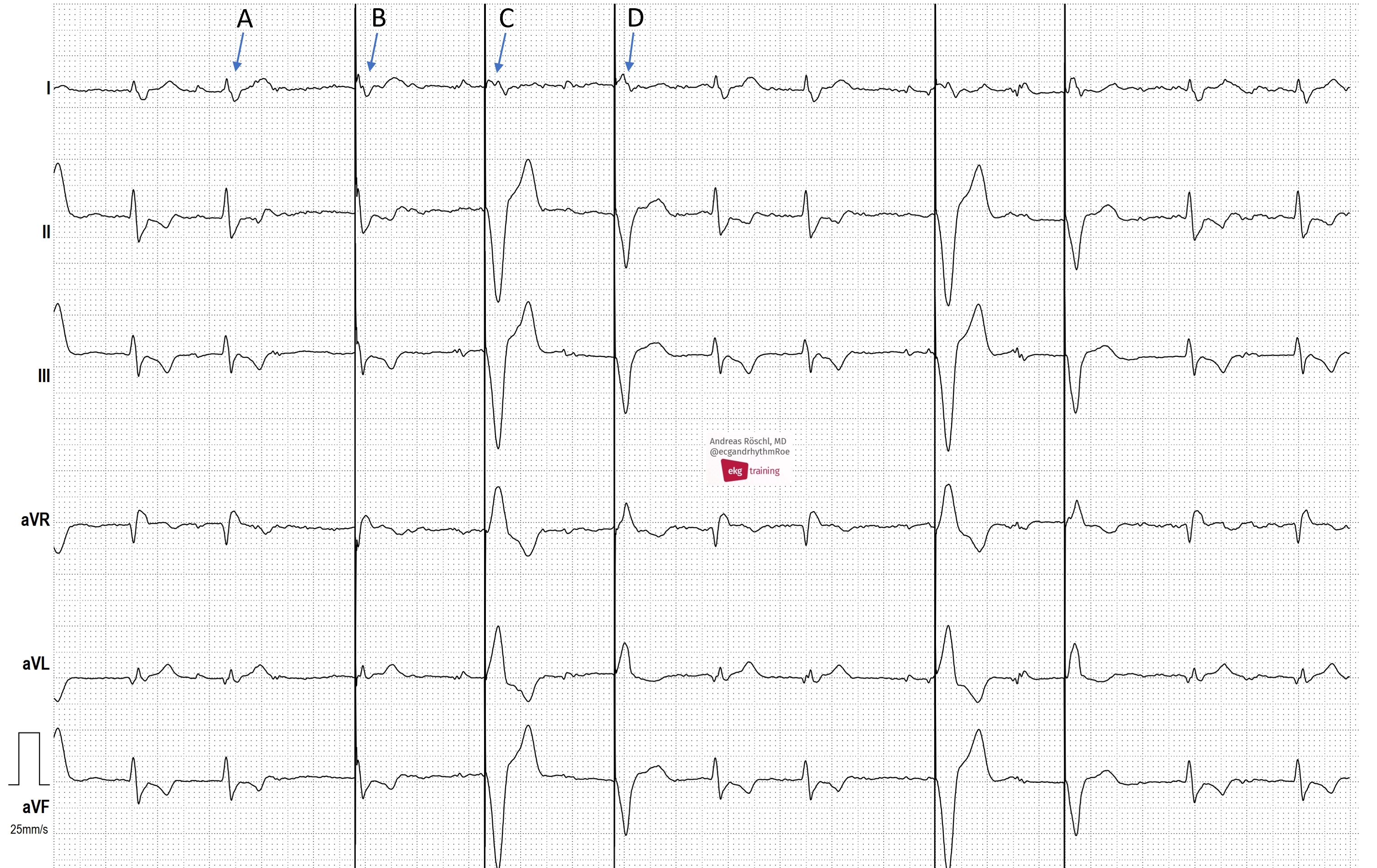
Second, the axis of the pseudo-malplacement tends to demonstrate a significant left axis deviation, between -30 ° and    -90 °. Since the right ventricle is activated first, the vector finishes by pointing up and to the left. If the wire were actually located in the left ventricle, the mean frontal axis would be to the right of +90 °

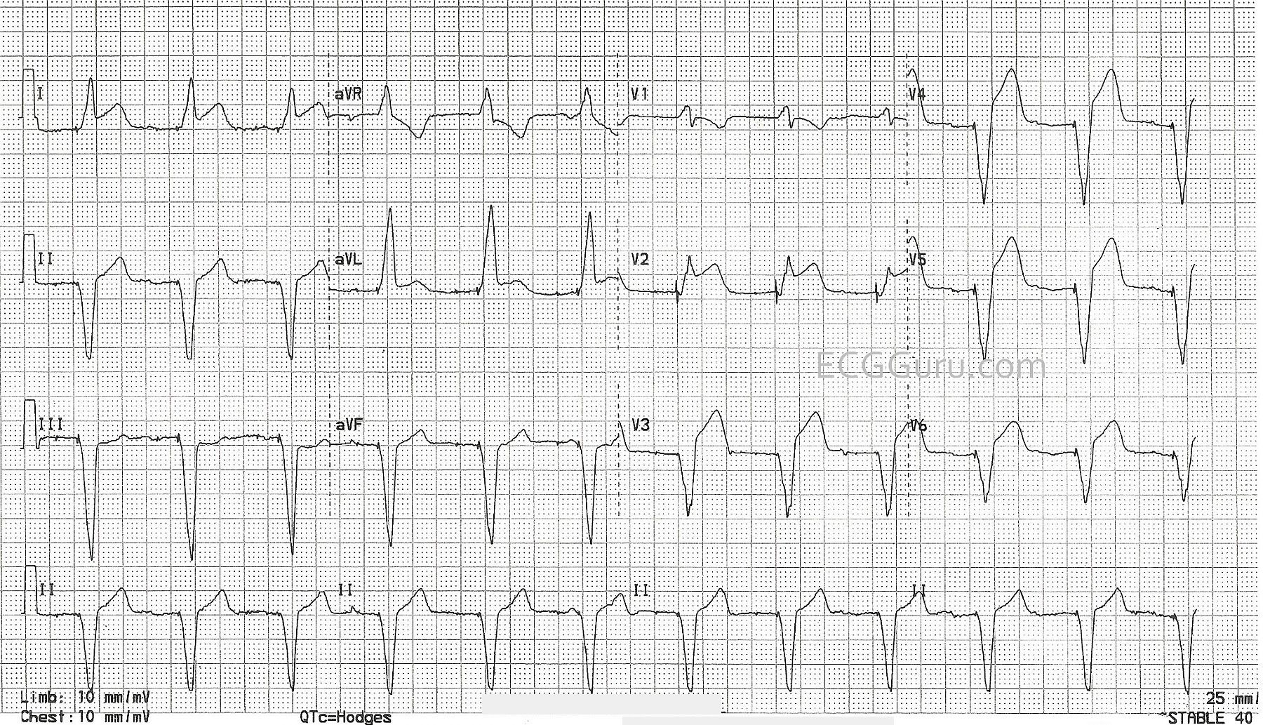
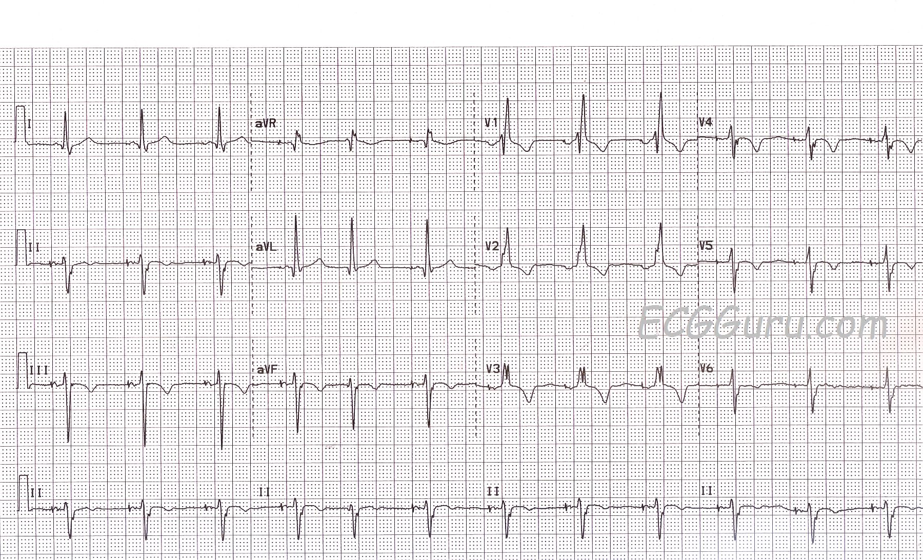
Third, when we look in the precordial leads, we know that Leads V1 and V2 overlie the right ventricle and leads V5 and V6 overlie the left ventricle. Leads V3 and V4 are in between. If the pacemaker wire is in the right ventricle, whatever is causing it to have an RBBB pattern in V1 will disappear before V3. A pacemaker wire in the right ventricle will show a LBBB pattern (QS) by Lead V3. If the wire is truly in the left ventricle, the RBBB pattern will extend to V3 and usually beyond. So a quick check is this: if you see a RBBB pattern in V1 in a pacemaker patient, look at V3. If the RBBB pattern is in V3 also, the wire is truly in the left ventricle. If V3 has a predominately negative QRS (QS), the wire is safely in the right ventricle where it is supposed to be. 

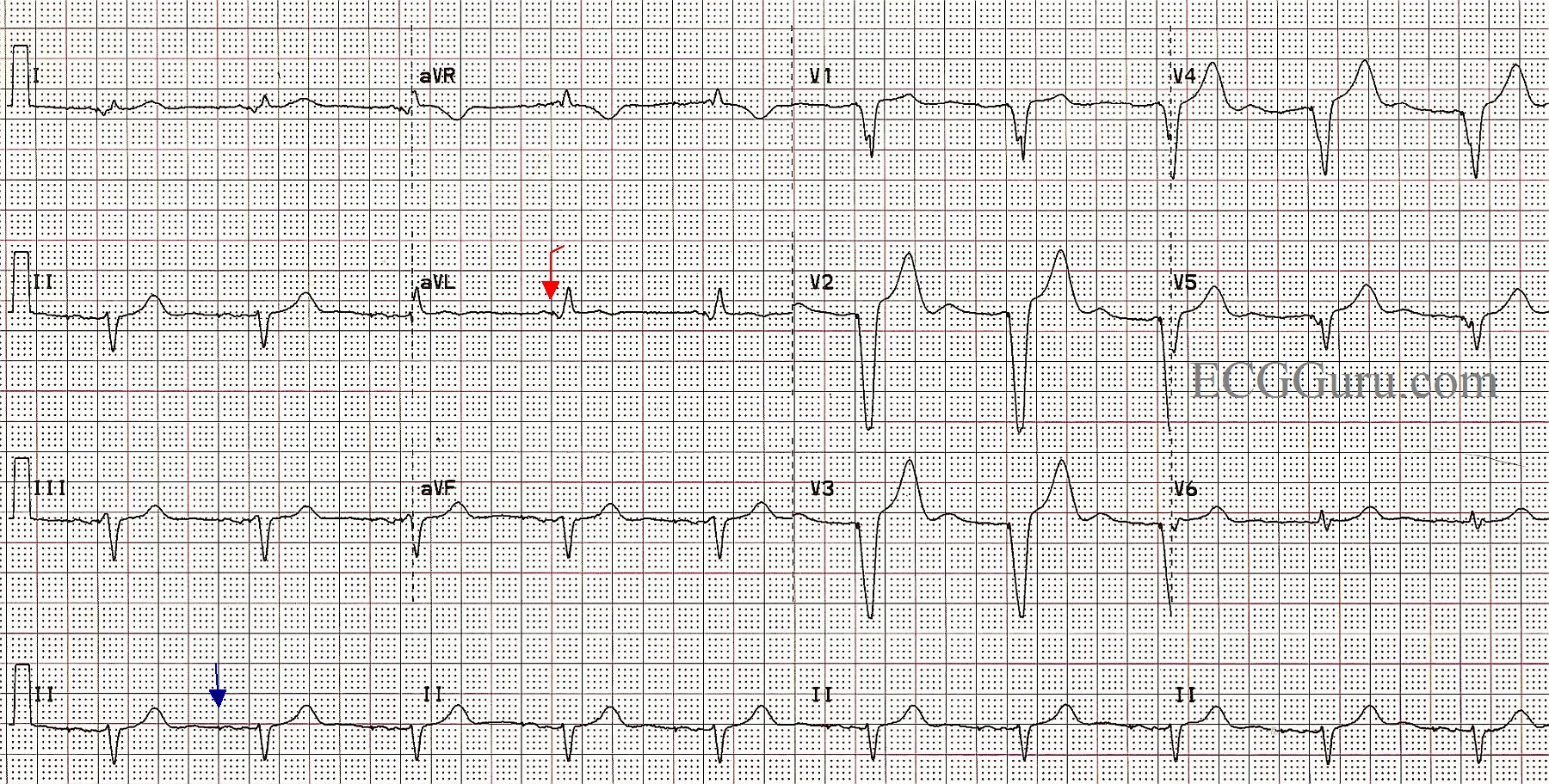
A fourth check is to look for an S wave in Lead I. Remember: one of the most characteristic features of RBBB is that slurred S wave in Lead I (as well as the other left-sided leads). If the ECG shows an RBBB pattern in V1 and an S wave is present in Lead I, then that is most likely a real RBBB pattern and the wire has somehow made its way into the left ventricle.

Pseudo Malplacement of Pacemaker Wire


Dawn's picture

Acute M.I. In Patient With Pacemaker

This ECG is taken from an elderly man who has a history of complete heart block and AV sequential pacemaker.  On the day of this ECG, he presented to the Emergency Department with chest pain and shortness of breath. His vital signs were stable and within normal limits.  We do not have information about his treatment or outcome. 

I don’t see spikes.  How do we know this is a paced rhythm?  The ECG clearly shows the presence of an AV pacemaker.  There are very tiny pacer “spikes”, probably best seen in Leads III, aVF, aVL, and most of the precordial leads.  Other ECG signs that this is a paced rhythm are:  wide QRS at about .16 seconds (160 ms); abnormal left frontal plane axis; regular rhythm with AV dissociation (there are P waves seen occasionally that have no fixed relationship to the QRS complexes).  Also, V6 is negative.  That rules out left bundle branch block unless the electrodes are misplaced.  There are no capture beats in this strip.  The patient appears to be, at least right now, 100% dependent on the paced rhythm. 

Why does the presence of a pacemaker make it harder to diagnose an M.I. from the ECG?  Wide-QRS rhythms, such as right-ventricular paced rhythms, left bundle branch block, and ventricular ectopic rhythms, usually have “discordant ST and T wave changes”.  That is, when the QRS is positive (upright), the ST and T wave are negative.  The reverse is also true:  when the QRS is negative and wide, the ST and T wave changes are positive (ST elevation).  This is not true for right bundle branch block because the conduction delay that causes the widening of the QRS is in the right ventricle, and the ST segment is reflecting the LEFT ventricle’s repolarization.  Discordant ST changes can make it difficult to determine from the ECG alone that there is an ST elevation M.I. (STEMI).  Diagnosis usually must be made from patient presentation, ECG changes over time, and cardiac enzymes – or more definitively from cardiac angiogram. Pacemakers that produce narrow QRS complexes do not cause discordant ST changes. 

Dawn's picture

Transcutaneous Pacemaker: Failure to Capture and False QRS Artifact

 When using a transcutaneous pacemaker, it is important to remember that the pacing stimulus can cause an artifact on the ECG.  This artifact is sometimes confused for a QRS complex.  Also, the pacing of the chest wall muscles can be misinterpreted as a pulse.  A “real” QRS complex will have a T wave. 

In this strip, the underlying sinus bradycardia is uninterrupted across the strip.  The rate is very slow – in the 30’s. 

At the beginning of the strip, there are four pacing stimuli, with artifact.  The pacemaker is in fixed mode.  It does not sense the normal QRS that occurs after the second pacing stimulus.  There is failure to sense AND failure to capture.  Apparently, the pacing is stopped, then the pacer is set to “demand” mode.  The pacemaker is sensing the patient’s native beats, but not pacing.  It is likely that the rate and/or the MA, or milliamps, need to be increased to achieve pacing with capture.

 This is a good ECG to illustrate the artifact that is possible with transcutaneous pacing, and remind your students not to assume the patient is being paced.  The patient’s clinical signs (skin perfusion, blood pressure, mentation) should be used to determine whether the rate is adequate.


Dawn's picture

Paced Rhythm Following AV Node Ablation

This ECG is taken from a woman who had suffered for several years with intractable intermittent atrial fibrillation. She had tolerated medications poorly, and several attempts at electric cardioversion had resulted in only temporary relief. Ultimately, she chose to undergo AV node ablation.  In the electrophysiology lab, her AV node was destroyed, preventing the atrial fib impulses from penetrating into the ventricles.  This resulted in a “man-made” complete AV block.  A pacemaker was implanted in the EP lab.  When she is in atrial fibrillation, the fibrillatory waves of the atria INHIBIT the atrial pacing electrode from firing, so she has no paced P waves at that time.  The right ventricular pacing electrode functions without inhibition, and makes a wide QRS complex with a leftward axis deviation (normal for RV pacing). 

In this ECG, we see the patient WITHOUT atrial fib, and the pacemaker is pacing the atria AND the ventricles, in a sequential fashion.  The spikes are very hard to see, as this is a “bipolar” pacemaker, which makes much smaller spikes than a “unipolar” pacemaker.  Some ECG machines will automatically enhance the spikes, but this one did not.  We have marked a “sample” atrial spike in blue for you and one of the ventricular spikes in red.  Each beat on this ECG actually has appropriately-timed atrial and ventricular stimuli (spikes), and the patient has optimized cardiac output provided by the “atrial kick”. A P wave occurring just before a QRS indicates that the ventricles are filling from the forceful contraction of the atria.  This provides much better filling than when the atria are not beating or are fibrillating. 

This is a good ECG to use to show your students how we can recognize a paced rhythm without being sure of the spikes.  Of course, without other evidence (patient history and exam), we can’t know for sure that this is a paced rhythm, but the steady, normal rate, wide complexes, and left axis deviation are signs of RV pacing.  Look for negatively-deflected QRS complexes in II, III, and aVF and positive QRSs in aVL and aVR. 

When pacing only one ventricle, the impulse travels relatively slowly through the other ventricle, resulting in wide QRS complexes.  This then results in SECONDARY ST-T WAVE CHANGES.  Wherever the QRS is positive, you will normally see some ST depression and T wave inversion.  In leads with negative QRS complexes, the opposite is true, and you will see ST elevation and upright T waves.  This can make evaluation of ST segments for acute M.I. difficult.


Dawn's picture

Atrial Pacing

This is a good example of an AV Sequential pacemaker in a patient with an intact AV conduction system.  The pacemaker is pacing the right atrium, and the impulse is being transmitted normally down through the AV node and the interventricular conduction system.  The pacer spike is seen before the P waves, and the QRS complex is narrow, reflecting normal conduction through the ventricles.

If you are teaching about ST elevation MI, this patient has no ST elevation M.I., but this type of pacing does not affect the ST segments, and an M.I. will still show as ST elevation.

Dawn's picture

Anti-tachycardia Function of ICD

This ECG was donated to the ECG Guru by Brent Dubois, and was originally published on the FaceBook page, Paramedic Tips & Tricks.  We published it to this site three years ago, but believe it should be shown again, as it is somewhat rare to catch a good-quality 12-Lead ECG of an implanted cardioverter-defibrillator pacemaer using overdrive pacing to terminate a ventricular tachycardia.  Most of our examples have been rhythm strips.

In this strip, we see the patient in ventricular tachycardia (V tach) at a rate of about 190 / minute.  The ICD, in response to the fast rate, delivers a short burst of even faster paced beats.  The physological rule in the heart is, "the fastest pacemaker controls the heart".  Once the pacemaker has terminated the V tach, it paces at a much slower rate.  It is pacing the atria, and the conduction system is intact, allowing the impulse to travel normally through the ventricles.  If the sinus node is able to "outpace" the slower paced rhythm, the heart will resume a sinus rhythm.

This is called "overdrive pacing" and is done automatically by an ICD that is programmed to do so.  Overdrive pacing can also be accomplished by a temporary transvenous pacer or transcutaneous pacemaker.  

Dawn's picture

Atrial Pacing With Right Bundle Branch Block

No instructor's collection should be without an atrial paced rhythm OR a right bundle branch block.  Here, you get both.  First, the atrial pacing.  This patient had a sinus node problem, but his AV conduction system was functional (if not perfect).  At this time, he is able to conduct impulses from the atria to the ventricles.  What he cannot do is reliably produce the impulse in his atria.   So, this pacemaker is currently pacing the right atrium, producing a paced "P" wave, which is then conducted to the ventricles.  The fifth beat on the strip shows a "native" beat - one produced by the patient.  No P wave is seen, so it is presumed to be a junctional beat.

As for conduction through the ventricles, there is a right bundle branch block.  The left bundle branch is ensuring that the ventricles receive the depolarization "message", and the ventricles are depolarizing and contracting.  However, the right ventricle gets the message a little late, since is arrives from the left ventricle, and not through a functioning right bundle branch.  This produces a terminal wave on each QRS that represents this delayed depolarization of the right ventricle.  In leads oriented to the left side of the heart, like I and V6, it is seen as a wide little S wave.  In V1, which is oriented to the patient's right, we see an R prime (R'), producing the easily-recognizable rSR' pattern of RBBB.

For your more advanced students, this patient has atypical T waves for RBBB.  Normally, the T waves axes should be OPPOSITE that of the terminal portion of the QRS.  So, Lead V1 correctly shows an inverted T wave, since the R' is a positive deflection.  There are inverted T waves in Leads III, aVF (II is biphasic), as well as in V4, V5, and V6.  We expected upright T waves here. Because we do not have clinical information for this patient, we will call them "non-specific" T wave changes, remembering that inverted T waves can be a sign of ischemia.

ALSO:  As noted in Dave Richley's comment below, there is a left axis deviation, with a negative Leads II, aVF and III, and a positive I and aVL.  This  indicates left anterior fascicular block, which is rather common with RBBB, since the right bundle branch and the left anterior fascicle share a blood supply. So, this person as a "bi-fascicular block". 


Dawn's picture

ECG Basics: Pacemaker Failure to Capture

This ECG is taken from a patient with an implanted pacemaker who was experiencing near-syncope.  She was taken to the hospital by EMS, where the pacemaker was adjusted to obtain ventricular capture.  This ECG did not have a Lead II rhythm strip, so the 12-lead ECG is being presented.  The P waves have been marked with a "P", pacemaker spikes marked with an arrow, and the QRS complexes marked with a "J" because they are junctional.  Because we can see 12 leads, or viewpoints, the morphology of the P waves and QRS complexes changes each time the machine switches to a new lead.

The underlying rhythm is sinus, with nearly regular P waves occuring at a rate of about 72 beats per minute.  The QRS complexes are also regular, but they are dissociated from the P waves.  Because the rate is near or just under 40 bpm, and the QRS complexes are narrow, this represents a slow junctional rhythm.  Because both atrial and ventricular rhythms are regular, but not associated with each other, an interpretation of complete heart block (third-degree AV block) can be made.  This explains why the patient had a pacemaker implanted.

The pacer spikes, for the most part, track the P waves, which is how this pacemaker is programmed.  They are not followed by a paced QRS complex, however.  This is failure to capture.  The second and fourth P waves did not stimulate a pacer spike because of their proximity to the T wave of the junctional beat.  The mA (energy setting) was adjusted in the Emergency Dept., and the pacemaker did not require repositioning.  The patient regained a reliable paced rhythm.

This section of the ECG Guru is meant to be for your basic students.  Pacemakers now have become very complex, with many options and variable settings.  So complex, that I would not feel comfortable getting into any more detail than I have here (although visitors to the site are welcome to).  It is important that, if you deal with patients in an emergency setting, you do not tell the patient that "something is wrong with their pacemaker" until it has been evaluated by a qualified person who can electronically interrogate the device.  It can be very difficult to determine from an ECG how a pacemaker is programmed, and how it should be reacting.  Since this patient had symptoms related to the bradycardia, and since pacemaker spikes occurred free of any refractory period and did not produce QRS complexes, it is safe to say there needs to be an adjustment.

In an emergency, with serious symptoms present, a transcutaneous or transvenous temporary pacemaker can be used.  Medications such as Atropine, epinephrine, and norepinephrine are also used, depending upon the type of AV block and the resources available.


Dawn's picture

ECG Basics: NIPS Procedure, ICD Test

This is a rhythm strip from a NIPS procedure (non-invasive programmed stimulaltion), which is a programming test for an implantable cardioverter defibrillator (ICD).  The test is done under light anesthesia, similar to that used for colonoscopy.   In this example, the patient is in normal sinus rhythm at the beginning of the procedure.  The pacemaker technician overdrives the patient's rate to observe the pacing function, then a stimulus is delivered to cause ventricular fibrillation (V Fib).  Initially, the ventricular rhythm is somewhat organized and coarse (V flutter), but it will rapidly deteriorate if not corrected.  Before it deteriorates, the ICD delivers a shock, and the patient's rhythm is restored.  In this example, bi-ventricular pacing was conducted for a few minutes before the patient resumed NSR.  The patient is then recovered from the anesthesia and discharged home.

For your students, this is a good example of the relative safety of shocking the well-perfused heart.  Although it is possible to put the heart into an intractable V Fib with this test, the ICD usually is able to convert the potentially lethal rhythm easily.  It is a good reminder that we need to perfuse the heart well before performing defibrillation on a person with unwitnessed cardiac arrest.

Pages

All our content is FREE & COPYRIGHT FREE for non-commercial use

Please be courteous and leave any watermark or author attribution on content you reproduce.